
Distribution center and warehouse layout design is dominated by the “right” angle – 90 degrees – known as the right angle for being correct for so many construction tasks. Whether in the X,Y or Z direction, cases, pallets, pallet rack components, shelving units, aisles, walls, building column grids, etc. are typically either parallel or perpendicular to each other. Is it not true that the most ideal DC sites are flat rectangles?
Partly due to this, traditional two dimensional drafting is still perfectly effective to complete most of our design work. The layout plan view with elevations and some side views give us most of the dimensional information needed to set up a facility.
 AutoCad 3D modelling has an important role in warehouse design however. We find CAD modelling to be most useful for equipment and features that stray from the right angle. Complex conveyor and sortation systems should be modelled in 3D to ensure that multiple levels of conveyor with curves, inclines, chutes, and spirals do not interfere with other components, walkways, racks, mobile equipment, etc. (Figure 1). One of the biggest selling points for the use of 3D CAD in any industry is that it helps to avoid costly design mistakes. For us, at the conceptual level it’s a useful, sometimes indispensable, design tool.
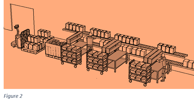
 The 3D model is powerful when used to illustrate concepts or processes involving clusters of different equipment, how they occupy space, work together and perform ergonomically (Figure 2). Multiple views are easy to generate. Any element can be removed or added to improve clarity. The point is not to create a time-consuming photorealistic rendering but rather an accurate block style 3D sketch.

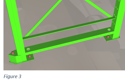
Detailed 3D images are also useful. Figure 3 shows a popular pallet rack upright base design for the end of an aisle. Features such as the wrap around deflector shoe, front and back double post and horizontal cross member with lag bolt access holes are clearly presented. It’s a helpful descriptive image and something not easy to convey in a 2D drawing world.
